Understanding the Differences Between Power Splitters, Dividers, and Combiners
Core Definitions
Power Splitters
What: Devices that take one input signal and split it into two or more outputs, often implying a simple, equal division.
Intent: Basic signal sharing across multiple paths, prioritizing ease and broadband capability.
Example: Splitting a TV signal to two screens.
Power Dividers
What: Similar to splitters, but typically engineered for precise power ratios (equal or unequal) with better control over loss and isolation.
Intent: Technical signal distribution in RF/microwave systems, often with performance specs in mind.
Example: Dividing a 5 GHz signal across an antenna array.
Power Combiners
What: Devices that take multiple input signals and merge them into one output.
Intent: Aggregate signals from multiple sources, often with phase or isolation considerations.
Example: Combining signals from two transmitters into one antenna.
Quick Note: “Splitter” and “divider” are often synonymous in practice, but “divider” leans toward engineered designs (e.g., Wilkinson), while “splitter” suggests simpler, generic use. Combiners are inherently about merging, not splitting.
Key Differences
Direction of Signal Flow
Splitters/Dividers: Input → Multiple outputs. One source feeds many destinations.
Combiners: Multiple inputs → One output. Many sources feed one destination.
Caveat: Many designs (e.g., Wilkinson, hybrids) are reciprocal—they work as splitters or combiners depending on how you hook them up.
Design Complexity
Example: A rat-race hybrid combining two phased signals.
Example: Wilkinson divider (3 dB split, 0.5 dB extra loss).
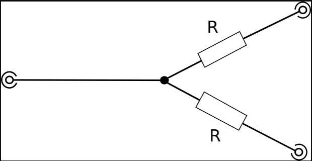
Example: A resistive 2-way splitter (6 dB total loss).
Splitters: Often basic—think resistive networks or T-junctions. Minimal focus on isolation or phase.
Dividers: More sophisticated, with transmission lines or hybrids for low loss and isolation.
Combiners: Similar to dividers but optimized for merging, often requiring phase alignment or isolation between inputs.
Power Split Ratio
Splitters: Usually equal (e.g., 3 dB per port for 2-way), though some are unequal by design.
Dividers: Can be equal (3 dB) or unequal (e.g., 10 dB vs. 1 dB), with precise control.
Combiners: N/A for splitting, but they handle input power ratios based on design (equal or weighted).
Isolation Between Ports
Splitters: Often none (e.g., resistive or T-junction). Output ports “see” each other, risking crosstalk.
Dividers: High isolation (20-30 dB) in designs like Wilkinson or hybrids, reducing interference.
Combiners: Isolation between input ports is key (e.g., 20 dB in a hybrid), preventing signal bleed-back.
Why It Matters: Isolation is critical in phased arrays or multi-transmitter setups.
Insertion Loss
Splitters: High loss in resistive types (e.g., 6 dB for 2-way due to resistors). Reactive/T-junction lower but still split-limited.
Dividers: Lower extra loss (0.1-0.5 dB beyond split) in Wilkinson or hybrid designs.
Combiners: Similar to dividers—loss depends on type, but reciprocal designs mirror divider specs.
Bandwidth
Splitters: Resistive types are broadband (DC to GHz), T-junctions less so.
Dividers: Narrowband (e.g., Wilkinson at 10% of center freq) unless multi-sectioned for broadband.
Combiners: Same as dividers—bandwidth tied to design (e.g., hybrid at 5 GHz vs. broadband resistive).
Phase Relationship
Splitters: Usually in-phase outputs unless specified (e.g., resistive).
Dividers: Can be in-phase (Wilkinson) or phase-shifted (90°/180° in hybrids).
Combiners: Phase alignment is critical—90°/180° options for beamforming or differential combining.
Practical Examples
Resistive Splitter: Splits a 1 GHz test signal to two oscilloscopes. 6 dB loss, no isolation, broadband.
Wilkinson Divider: Divides a 28 GHz 5G signal for two antennas. 3 dB split, 25 dB isolation, low loss.
Hybrid Combiner: Merges two 10 GHz radar returns with 90° phase shift for beam steering. 20 dB isolation.
Vs. Directional Couplers (Quick Clarification)
Splitters/Dividers: Distribute power to all outputs, no directional sampling.
Combiners: Merge signals, no sampling intent.
Couplers: Sample a fraction (e.g., 10 dB) with high directivity, not full distribution.
Overlap: A 3 dB hybrid can split or combine, blurring lines—but couplers prioritize monitoring.
Real-World Take
Splitters: Cheap, simple, lossy—great for non-critical apps (e.g., splitting audio feeds).
Dividers: Engineered for precision—think RF systems where isolation and loss matter (5G, radar).
Combiners: Dividers in reverse, but with extra care for input interactions (MIMO, power amps).
The industry sometimes overcomplicates with “next-gen” dividers, but a basic resistive splitter still works for quick jobs—don’t overhype the fancy stuff.

Email us
Warning: Undefined variable $pronamepx in D:\wwwroot\www.resistorsupplies.com\moban\en_inc\ziliao.php on line 67
Fatal error: Uncaught TypeError: count(): Argument #1 ($value) must be of type Countable|array, null given in D:\wwwroot\www.resistorsupplies.com\moban\en_inc\ziliao.php:67 Stack trace: #0 D:\wwwroot\www.resistorsupplies.com\ziliao.php(146): include() #1 {main} thrown in D:\wwwroot\www.resistorsupplies.com\moban\en_inc\ziliao.php on line 67
