Understanding Common Mode Chokes: Principles and Applications
Common mode chokes (CMCs) are key players in RF, microwave, and power electronics, designed to tackle common mode noise—unwanted signals that appear simultaneously and in-phase on both lines of a differential pair (e.g., power lines or data cables). They’re simple in concept but powerful in application, filtering out interference while letting desired signals pass. Let’s dive into their principles and applications, keeping it practical and grounded.

Principles of Common Mode Chokes
What They Are
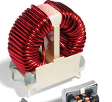
A CMC is essentially an inductor with two (or more) windings on a shared magnetic core—typically ferrite. The windings are arranged so that currents flowing in the same direction (common mode) see high impedance, while currents flowing in opposite directions (differential mode) see almost none.
How They Work
Net flux ≈ 0, so the choke “ignores” the signal.
Impedance: Z=2πfLZ = 2pi f LZ=2πfL, where LLL is the choke’s inductance, and fff is the noise frequency.
Common Mode (CM) Current: When noise currents flow in the same direction on both lines (e.g., from EMI pickup), the magnetic fields from each winding add up in the core. This creates a high inductance (and thus high impedance), choking the noise.
Differential Mode (DM) Current: For the intended signal (opposite directions, like AC power or data), the fields cancel out in the core, resulting in near-zero inductance and minimal impedance.
Core Design
Material: Ferrite (e.g., Mn-Zn or Ni-Zn) for high permeability at RF/microwave frequencies (kHz to GHz).
Shape: Toroidal or E-core to maximize flux coupling and minimize leakage.
Turns: More windings = higher inductance, but also more parasitic capacitance (limiting high-frequency performance).
Key Parameters
Impedance: 100 Ω to 10 kΩ at target frequency (e.g., 100 MHz for RF noise).
Current Rating: Must handle the differential current without core saturation (e.g., 1 A to 20 A).
Frequency Range: Effective from kHz (power line noise) to GHz (RFI), depending on design.
Insertion Loss: How much CM noise is attenuated (e.g., 20-40 dB).
Limitations
Parasitic capacitance between windings reduces effectiveness at very high frequencies (>1 GHz).
Core saturation under high CM currents can kill performance.
Slight DM impedance (leakage inductance) can affect the desired signal if not minimized.
Applications in RF, Microwave, and Beyond
EMI/RFI Suppression
Where: Power supplies, USB cables, HDMI lines, Ethernet cables.
Why: Blocks external noise (e.g., from motors or radios) that couples onto both lines, preventing it from reaching sensitive circuits.
Example: A CMC on a 5 V USB line attenuates 100 MHz noise from a nearby Wi-Fi router, keeping data clean.
Type: Surface-mount ferrite choke (e.g., 600 Ω at 100 MHz).
Power Line Filtering
Where: AC/DC converters, inverters, solar panels.
Why: Stops CM noise from switching circuits (kHz range) from radiating or back-feeding into the grid.
Example: A 10 mH CMC in a 230 V AC supply filters 50 kHz switching noise, meeting EMC standards.
Type: Toroidal choke with high current rating (e.g., 5 A).
Differential Signal Integrity
Where: High-speed data lines (e.g., PCIe, SATA, CAN bus).
Why: Preserves signal quality by choking CM noise without distorting the differential signal.
Example: A CMC on an Ethernet cable (100 Mbps) kills 10 MHz CM interference from a power line nearby.
Type: Small bifilar-wound choke (e.g., 120 Ω at 100 MHz).
Antenna Feed Systems
Where: RF transceivers, HAM radio, satellite dishes.
Why: Prevents CM currents on coax shields (from unbalanced feeds) from radiating or degrading reception.
Example: A 1:1 balun (a CMC variant) at 14 MHz on a dipole antenna stops shield currents, improving pattern.
Type: Ferrite toroid with coax or wire windings.
Ground Loop Elimination
Where: Audio systems, industrial sensors.
Why: Breaks CM current paths that cause hum or noise in grounded setups.
Example: A CMC in a pro audio XLR line kills 60 Hz hum from a ground loop.
Type: Low-frequency choke (e.g., 10 mH).
Microwave Circuit Protection
Where: Amplifiers, mixers, radar front-ends.
Why: Suppresses CM noise on bias lines or RF paths, protecting sensitive components.
Example: A 1 GHz CMC on a 5G PA bias line blocks 100 MHz spurs from a nearby transmitter.
Type: High-frequency ferrite bead or choke.
Real-World Context
RF (1-1000 MHz): CMCs shine in radio and comms, tackling noise from 10 kHz EMI to 500 MHz RFI. Small SMD chokes dominate here.
Microwave (1-100 GHz): Less common due to parasitics, but high-freq designs (e.g., GHz-rated ferrites) still filter bias lines or low-end noise.
Power Systems: Heavy-duty toroids rule, handling amps and kHz noise with ease.
The establishment loves pushing “universal” high-spec CMCs, but a cheap ferrite bead often does the trick for basic RF cleanup—overkill isn’t always better. That said, in microwave or high-current apps, skimping on quality (e.g., low-saturation cores) can backfire.
Email us
Warning: Undefined variable $pronamepx in D:\wwwroot\www.resistorsupplies.com\moban\en_inc\ziliao.php on line 67
Fatal error: Uncaught TypeError: count(): Argument #1 ($value) must be of type Countable|array, null given in D:\wwwroot\www.resistorsupplies.com\moban\en_inc\ziliao.php:67 Stack trace: #0 D:\wwwroot\www.resistorsupplies.com\ziliao.php(146): include() #1 {main} thrown in D:\wwwroot\www.resistorsupplies.com\moban\en_inc\ziliao.php on line 67
