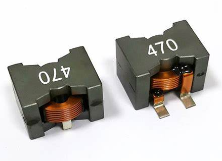
High Current Power Inductors: Design and Applications
High current power inductors are heavy-duty components built to handle significant current (think 10 A to 100s of A) while storing energy, filtering signals, or managing power in demanding systems. Unlike standard inductors, their design prioritizes low resistance, high saturation tolerance, and thermal resilience—crucial for power electronics like SMPS, motor drives, or renewable energy setups. Let’s dive into their design principles and applications, keeping it practical and focused.

Design Principles for High Current Power Inductors
Core Material Selection
Powdered Iron: High saturation (e.g., 1-2 T), moderate permeability (µ = 10-100), good for DC bias.
Ferrite: Higher µ (1000+), lower saturation (~0.4 T), better for AC filtering but less current capacity.
Metal Alloy (e.g., Sendust, MPP): Balanced saturation (0.8-1.5 T) and low core loss, premium choice.
Options:
Choice: Powdered iron or alloys for high current (e.g., 50 A); ferrite for lower current with high LLL.
Trade-Off: High-saturation cores cost more and have lower LLL per turn.
Inductance Value
L=N2μA/lL = N^2 mu A / lL=N2μA/l (N = turns, A = core area, l = path length).
Example: 100 µH at 20 A needs a big core and ~10-20 turns.
Goal: Store energy (E=12LI2E = frac{1}{2} L I^2E=21LI2) or filter ripple without saturating.
How:
Trade-Off: Higher LLL needs more turns or bigger cores, increasing size and resistance.
Current Handling (Saturation)
Use large cross-section cores (A) or gapped designs to spread flux.
Example: 50 A, 10 turns, 10 cm path → B<1TB < 1 TB<1T with powdered iron.
Goal: Avoid core saturation where B=μHI/lB = mu H I / lB=μHI/l hits BsatB_{ ext{sat}}Bsat.
How:
DC Bias: Inductance drops as DC current rises—design for 20-30% roll-off at max current.
Trade-Off: Bigger cores or gaps reduce saturation but lower LLL.
Low DCR (DC Resistance)
Thick wire (e.g., 14 AWG) or flat copper ribbon.
Short windings, high-conductivity materials (copper, not aluminum).
Goal: Minimize I2RI^2 RI2R losses for efficiency (e.g., <10 mΩ).
How:
Example: A 50 A inductor with 5 mΩ DCR drops 12.5 W—manageable with cooling.
Trade-Off: Low DCR means bigger wire, less room for turns.
Thermal Management
Open-core designs or potting for heat dissipation.
Temp rating: 125°C typical, 150°C for high-end.
Goal: Handle heat from core losses (hysteresis, eddy) and copper losses.
How:
Example: 20 A at 50 kHz generates ~5 W loss—needs airflow or heatsink.
Trade-Off: Cooling adds bulk or cost.
Frequency Response
Minimize parasitic capacitance (fewer turns, spaced windings).
Core loss rises with fff (e.g., P∝f2B2P propto f^2 B^2P∝f2B2). Use alloys for high freq.
Goal: Effective inductance at operating freq (e.g., 10 kHz-1 MHz in SMPS).
How:
Limit: Self-resonant freq (SRF) caps usability—keep operating freq <50% of SRF.
Construction
Types: Toroid (low EMI), drum (compact), or shielded (noise-sensitive apps).
Winding: Single-layer for low capacitance; multi-layer for high LLL if parasitics allow.
Size: 10 mm to 100 mm, scaling with current and LLL.
Applications in Power Systems
Switch-Mode Power Supplies (SMPS)
What: Smooth output ripple or store energy in buck/boost converters.
Why: Handles high current (e.g., 20 A) at 100 kHz-1 MHz.
Example: A 47 µH, 30 A inductor in a 12 V-to-5 V server PSU filters 500 kHz ripple.
Design: Metal alloy core, low DCR (~5 mΩ).
Motor Drives
What: Filter harmonics or limit inrush in VFDs (variable frequency drives).
Why: Manages 50-100 A at 10-50 kHz for smooth torque.
Example: A 1 mH, 80 A inductor in a 480 V industrial motor drive cuts 20 kHz noise.
Design: Powdered iron, gapped for saturation resistance.
Renewable Energy (Solar/Wind)
What: Energy storage and filtering in inverters.
Why: Handles high DC bias (e.g., 50 A) from PV panels or turbines.
Example: A 200 µH, 60 A inductor in a 1 kW solar inverter smooths 25 kHz PWM output.
Design: Large toroid, high saturation tolerance.
Electric Vehicles (EV)
What: Boost converters or filters in battery management/DC-DC systems.
Why: Supports 100s of amps at 50-400 V for chargers or traction.
Example: A 50 µH, 150 A inductor in a 400 V EV charger boosts efficiency.
Design: Shielded alloy core, ultra-low DCR (<1 mΩ).
Power Factor Correction (PFC)
What: Shape input current in AC-DC supplies.
Why: Aligns current with voltage, handling 10-50 A at 50-100 kHz.
Example: A 300 µH, 20 A inductor in a 230 V PFC circuit cuts harmonics.
Design: Ferrite or alloy, moderate LLL, high current.
UPS Systems
What: Stabilize output in battery-to-AC conversion.
Why: Manages 20-100 A during load surges.
Example: A 100 µH, 40 A inductor in a 5 kVA UPS filters 20 kHz switching.
Design: Toroid, robust thermal design.
Real-World Context
Current Range: 10 A (small PSUs) to 500 A (EV/grid apps).
Freq Range: 10 kHz-1 MHz typical; higher in niche SMPS.
Efficiency: 95-99% demands low DCR and core loss—every watt counts at 100 A.
Size: From SMD (5 A) to brick-sized (200 A)—space vs. performance trade-off.
The hype might push exotic alloys or monster inductors, but a basic powdered iron toroid often nails it for 20-50 A apps—don’t overspend unless saturation or heat demands it.
Email us
Warning: Undefined variable $pronamepx in D:\wwwroot\www.resistorsupplies.com\moban\en_inc\ziliao.php on line 67
Fatal error: Uncaught TypeError: count(): Argument #1 ($value) must be of type Countable|array, null given in D:\wwwroot\www.resistorsupplies.com\moban\en_inc\ziliao.php:67 Stack trace: #0 D:\wwwroot\www.resistorsupplies.com\ziliao.php(146): include() #1 {main} thrown in D:\wwwroot\www.resistorsupplies.com\moban\en_inc\ziliao.php on line 67
