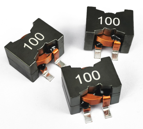
Selecting the Right High Current Power Inductor for Your Circuit
Selecting the right high current power inductor for your circuit is about matching the component’s specs to your application’s demands—current, frequency, efficiency, size, and cost all play a role. These inductors (handling 10 A to 100s of A) are critical in power supplies, motor drives, or EV systems, and picking the wrong one can mean saturation, overheating, or wasted money. Here’s a practical guide to nailing the choice, step-by-step.

Key Steps and Considerations
Define Current Requirements
Max DC Current (I_DC): Peak steady-state current the inductor must handle (e.g., 20 A in a PSU).
Peak Current (I_Peak): Short-term transients (e.g., 30 A spikes in a motor start).
Ripple Current (I_Ripple): AC component from switching (e.g., 20% of I_DC, or 4 A at 100 kHz).
What to Check:
Why: Core saturation happens when B=μNI/l>BsatB = mu N I / l > B_{ ext{sat}}B=μNI/l>Bsat. Include ripple in total current.
Example: For a 12 V, 20 A buck converter, pick an inductor rated for 24-26 A (20 A + 20% ripple + margin).
Tip: Datasheets list “saturation current” (I_sat)—where LLL drops 20-30%. Stay below it.
Set Inductance Value (L)
L=V⋅ΔtΔIL = frac{V cdot Delta t}{Delta I}L=ΔIV⋅Δt (V = voltage across inductor, ΔtDelta tΔt = switch time, ΔIDelta IΔI = ripple current).
Example: 12 V buck, 100 kHz (10 µs period), 40% ripple (8 A), on-time 50% → L=12⋅5⋅10−6/8=7.5 μHL = 12 cdot 5 cdot 10^{-6} / 8 = 7.5 , mu ext{H}L=12⋅5⋅10−6/8=7.5μH.
What to Calculate:
Why: Too low LLL = high ripple, stressing caps; too high = bigger size, more cost.
Range: 1-10 µH for high-freq SMPS (1 MHz); 100-1000 µH for low-freq (10 kHz) or high power.
Tip: Aim for 20-40% ripple of I_DC unless efficiency demands tighter control.
Check Frequency Compatibility
Core losses (P∝f2B2P propto f^2 B^2P∝f2B2) rise with frequency—ferrite struggles above 1 MHz; alloys shine.
Self-resonant freq (SRF) must exceed operating freq (e.g., SRF > 2 MHz for 1 MHz use).
What to Assess: Operating frequency (e.g., 100 kHz in SMPS, 1 MHz with SiC/GaN).
Why:
Example: A 47 µH, 30 A inductor with 5 MHz SRF works at 1 MHz; 500 kHz SRF fails.
Tip: High-freq needs low-parasitic designs (fewer turns, alloy cores).
Evaluate DC Resistance (DCR)
What to Target: Low DCR for efficiency (e.g., <10 mΩ for 20 A).
Why: Power loss = I2RI^2 RI2R. At 50 A, 5 mΩ = 12.5 W—heat kills if unchecked.
Example: A 20 A, 100 µH inductor with 8 mΩ loses 3.2 W—OK with airflow, not in a sealed box.
Tip: Flat wire or thick gauge cuts DCR but ups size—balance with LLL.
Assess Saturation and Thermal Limits
Temp rise (e.g., 40°C) + ambient (e.g., 50°C) < rating (125°C typical).
Example: 20 A, 5 W loss → 40°C rise needs cooling if ambient > 85°C.
Pick a core with BsatB_{ ext{sat}}Bsat (e.g., 1 T for powdered iron) above your max flux.
Example: 30 A, 10 turns, 10 cm path → needs large A or gap to keep B<1TB < 1 TB<1T.
Saturation:
Thermal:
Tip: Datasheets give “temperature rise current” (I_rms)—cross-check with I_sat.
Choose Core and Construction
Ferrite: Cheap, high LLL, saturates at 0.4 T—good for <20 A, low freq.
Powdered Iron: 1-2 T, moderate LLL, rugged—20-100 A staple.
Metal Alloy: 1-1.5 T, low loss, high freq—premium for 50 A+ or 1 MHz+.
Shielded: Low EMI, compact (e.g., SMD for PCBs).
Toroid: High LLL, low leakage, big for high current.
Options:
Example: 50 A, 200 µH solar inverter → powdered iron toroid; 20 A, 10 µH GaN PSU → shielded alloy.
Tip: Unshielded is fine if EMI’s controlled elsewhere.
Size and Cost Trade-Offs
Size: 10 mm SMD for 10 A; 50-100 mm toroids for 100 A. Fit your board or enclosure.
Cost: Ferrite = $1-5; alloys = $5-20; custom = $50+.
Example: A 30 A, 47 µH ferrite at $3 vs. alloy at $10—ferrite wins unless 1 MHz or density matters.
Tip: Don’t over-spec—20% headroom beats 50% overkill.
Verify Specs with Datasheet
Cross-check: I_sat > I_peak, DCR fits loss budget, SRF > 2× freq, temp rise fits environment.
Example: Coilcraft XAL1510-472 (47 µH, 34 A I_sat, 8 mΩ, 4 MHz SRF) for a 20 A, 1 MHz buck.
Application Examples
20 A Buck Converter (12 V to 5 V, 500 kHz): 10 µH, 25 A I_sat, 5 mΩ, shielded alloy—compact, efficient.
100 A EV Charger (400 V, 100 kHz): 50 µH, 120 A I_sat, 2 mΩ, powdered iron toroid—handles transients.
50 A Solar Inverter (48 V, 25 kHz): 200 µH, 60 A I_sat, 10 mΩ, unshielded ferrite—cost-effective.
Practical Tips
Margin: 20-30% above max current and ripple—saturation’s a cliff, not a slope.
Test: Measure LLL drop and temp rise under load—datasheets lie sometimes.
Cheap Wins: Oversized ferrite beats undersized alloy for low-freq, high-current jobs.
Avoid Traps: Tiny SMDs claiming 50 A often overheat—check thermals, not just I_sat.
The industry might push bleeding-edge alloys or GaN-ready inductors, but a basic powdered iron toroid still crushes it for 20-50 A at 100 kHz—match the tool to the job.
Email us
Warning: Undefined variable $pronamepx in D:\wwwroot\www.resistorsupplies.com\moban\en_inc\ziliao.php on line 67
Fatal error: Uncaught TypeError: count(): Argument #1 ($value) must be of type Countable|array, null given in D:\wwwroot\www.resistorsupplies.com\moban\en_inc\ziliao.php:67 Stack trace: #0 D:\wwwroot\www.resistorsupplies.com\ziliao.php(146): include() #1 {main} thrown in D:\wwwroot\www.resistorsupplies.com\moban\en_inc\ziliao.php on line 67
