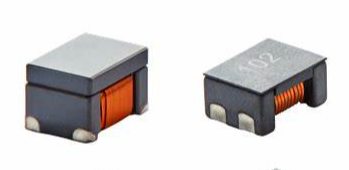
Understanding the Performance Characteristics of High Current Power Inductors

Understanding the performance characteristics of high current power inductors is crucial for picking the right one and ensuring it thrives in your circuit—whether it’s handling 10 A in a small PSU or 500 A in an EV charger. These inductors, built for modern power electronics, are judged on how they manage current, losses, frequency, and heat under stress. Let’s break down the key metrics, how they behave, and what they mean in practice, keeping it clear and grounded.
Key Performance Characteristics
Inductance (L)
Nominal LLL holds at low current but drops as DC bias increases due to core saturation.
Example: A 100 µH inductor at 0 A might fall to 70 µH at 50 A (30% roll-off).
What It Is: The ability to store energy in a magnetic field (LLL in µH or mH).
Behavior:
Measurement: Datasheets list LLL vs. current—check at your operating point.
Impact: Too low LLL = high ripple; too high = bigger size.
High-Current Twist: Must stay functional at 20-500 A without collapsing.
Saturation Current (I_sat)
Depends on core: ferrite saturates at ~0.4 T (~20 A); powdered iron at 1-2 T (~100 A).
B=μNI/lB = mu N I / lB=μNI/l hits BsatB_{ ext{sat}}Bsat—more turns or smaller core = earlier saturation.
What It Is: Max current where LLL drops significantly (e.g., 20-30% from nominal).
Behavior:
Example: A 47 µH, 30 A I_sat inductor holds at 25 A but tanks at 35 A.
Impact: Exceed I_sat, and ripple spikes, efficiency plummets—game over.
Key: High-current apps need I_sat 20-30% above peak (DC + ripple).
DC Resistance (DCR)
Fixed value (e.g., 5 mΩ), but loss scales with current squared.
Example: 50 A through 5 mΩ = 12.5 W heat—major at high current.
What It Is: Resistance of the windings (mΩ), causing I2RI^2 RI2R loss.
Behavior:
Measurement: Listed in datasheets—lower with flat wire (e.g., 2 mΩ vs. 10 mΩ round).
Impact: Low DCR = high efficiency, but big wire cuts turn count or ups size.
High-Current Twist: Critical at 100 A—1 mΩ vs. 5 mΩ is 10 W vs. 50 W loss.
Temperature Rise Current (I_rms)
Driven by total losses: copper (I2RI^2 RI2R) + core (hysteresis, eddy).
Example: 20 A, 5 mΩ, 3 W loss → 30°C rise in open air, 50°C in a box.
What It Is: Max RMS current before temp rise exceeds spec (e.g., 40°C rise).
Behavior:
Impact: Over I_rms, you hit thermal limits (125°C typical)—meltdown risk.
Key: High-current designs need cooling or high-temp ratings (150°C).
Core Loss
Scales with f2B2f^2 B^2f2B2 (f = freq, B = flux density).
Ferrite: low loss <500 kHz; alloys: better at 1-5 MHz.
Example: 100 µH, 20 A, 1 MHz → 2-5 W loss in alloy vs. 10 W in ferrite.
What It Is: Power lost in the core from AC flux (hysteresis, eddy currents).
Behavior:
Impact: High freq + high current = heat bomb without low-loss cores.
High-Current Twist: Ripple at 50 A amplifies this—needs alloys or SMC.
Self-Resonant Frequency (SRF)
Lower with more turns or tighter windings (e.g., 2 MHz for 47 µH, 10 MHz for 10 µH).
What It Is: Freq where parasitic capacitance makes it a capacitor, not an inductor.
Behavior:
Example: 1 MHz SMPS needs SRF >2 MHz—5 MHz SRF works, 1.5 MHz fails.
Impact: Above SRF, LLL collapses—useless for filtering.
Key: High-freq apps (e.g., GaN) demand high SRF.
Leakage Inductance and EMI
Higher in unshielded designs (e.g., 1% of LLL); near-zero in shielded.
What It Is: Unwanted LLL not coupled to the core, radiating noise.
Behavior:
Example: 100 µH unshielded at 50 A radiates 100 kHz noise—RF gear hates it.
Impact: Shielded cuts EMI but ups cost/size—trade-off matters.
High-Current Twist: Big currents amplify EMI—shielding’s often a must.
Power Handling
Limited by saturation, DCR, and heat.
Example: 100 A, 50 µH, 100 kHz → ~1 kW capacity in a toroid.
What It Is: Total power throughput without failure (current × voltage drop).
Behavior:
Impact: EVs or inverters need kW-range inductors—size and cooling scale up.
Key: High current pushes physical limits—design margins are tight.
Performance in Context
20 A SMPS (500 kHz): 47 µH, I_sat = 25 A, DCR = 8 mΩ, SRF = 4 MHz—low loss, compact.
100 A EV Charger (100 kHz): 50 µH, I_sat = 120 A, DCR = 2 mΩ, 40°C rise—handles transients.
50 A Solar Inverter (25 kHz): 200 µH, I_sat = 60 A, DCR = 10 mΩ—cost-effective, high LLL.
1 MHz GaN PSU: 10 µH, I_sat = 30 A, SRF = 10 MHz—high-freq stability.
High-Current Challenges
Saturation: 100 A+ needs big cores or alloys—ferrite taps out early.
Heat: 20 W loss at 50 A demands cooling—ambient matters (50°C vs. 85°C).
Freq: 1-5 MHz with SiC/GaN pushes parasitics—low-loss cores or bust.
Size: High LLL and current = bulky; planar types fight this but cost more.
Practical Takeaways
I_sat > Peak: 20-30% headroom—50 A peak needs 60-65 A I_sat.
DCR Drives Loss: 1 mΩ saves watts at 100 A—don’t skimp on wire.
Freq Caps SRF: 1 MHz needs >2 MHz SRF—check it.
Thermobile: Test under load—40°C rise on paper ≠ real life.
The hype might oversell “perfect” alloy inductors, but a basic powdered iron toroid still rules 20-50 A at 100 kHz—match the spec, not the buzz.
Email us
Warning: Undefined variable $pronamepx in D:\wwwroot\www.resistorsupplies.com\moban\en_inc\ziliao.php on line 67
Fatal error: Uncaught TypeError: count(): Argument #1 ($value) must be of type Countable|array, null given in D:\wwwroot\www.resistorsupplies.com\moban\en_inc\ziliao.php:67 Stack trace: #0 D:\wwwroot\www.resistorsupplies.com\ziliao.php(146): include() #1 {main} thrown in D:\wwwroot\www.resistorsupplies.com\moban\en_inc\ziliao.php on line 67
