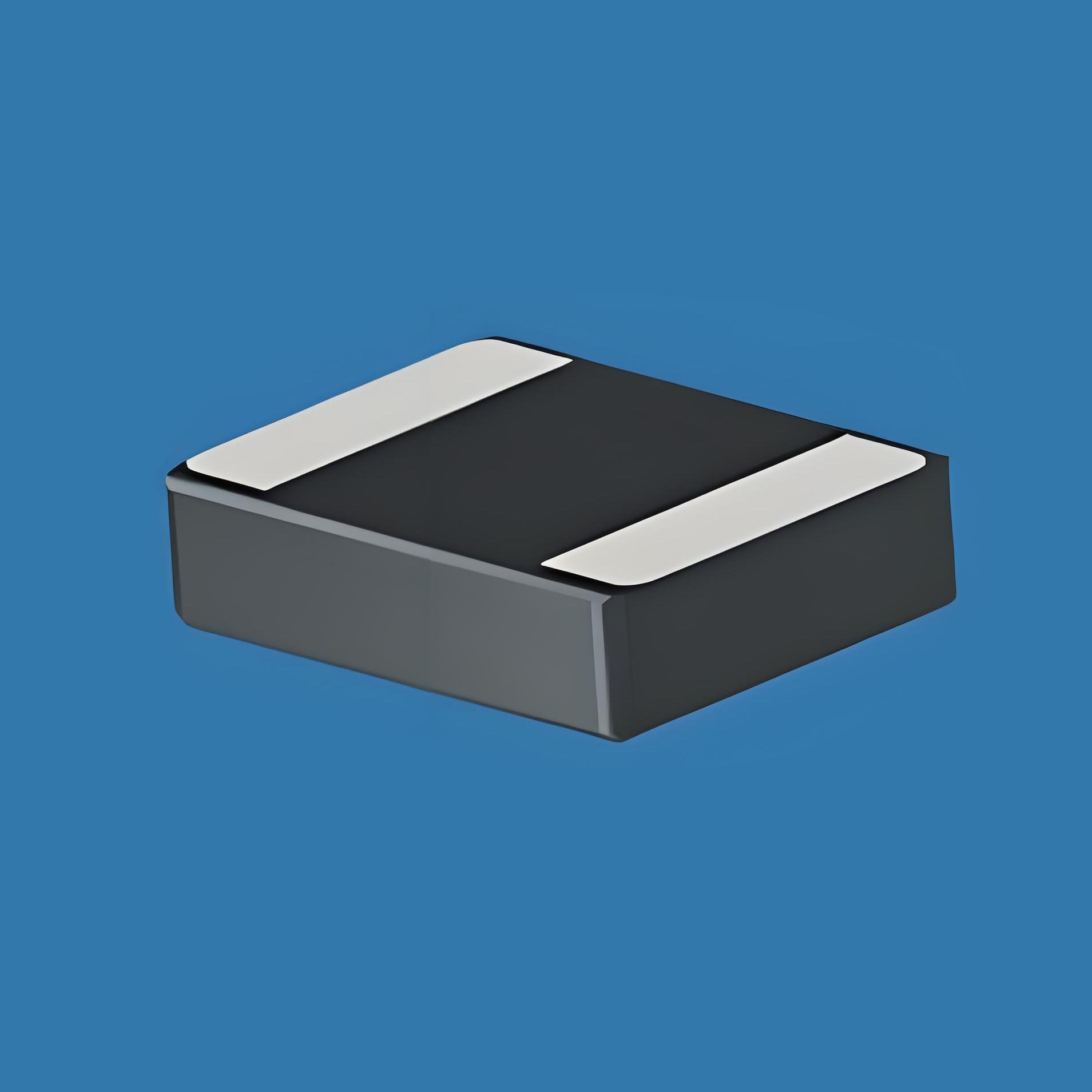
High-Current Wide-Wound Chip Inductor Selection Guide
Designers often struggle to find a high-current wide-wound chip inductor that meets both saturation-current and DCR limits while still fitting into compact footprints. This guide provides a clear selection path, exact part-to-part comparisons, and practical design tips so you can pick the right SMD component in minutes—not days.

1. Why Wide-Wound Chip Inductors Matter
Wide-wound construction increases conductor cross-section, lowering DC resistance (DCR) and pushing saturation current (ISAT) above 10 A in footprints as small as 7 mm × 7 mm. This makes them ideal for high-current buck converters, PoE PSE controllers, and automotive LED drivers where every milliohm counts.

2. Key Specifications in Plain English
| Spec | What It Tells You | Typical Range | Watch-Out |
|---|---|---|---|
| ISAT | Current where inductance drops 30 % | 5 A – 80 A | Check at 100 °C, not 25 °C |
| DCR | Copper losses → heat | 0.4 mΩ – 15 mΩ | Multiply by IRMS² |
| SRF | Freq where part turns capacitive | 1 MHz – 15 MHz | Keep switching freq ≤ SRF/10 |
| Footprint | L×W in mm | 4×4 – 12×12 | Height often 4 mm – 8 mm |
3. Datasheet-Level Comparison Table (Popular 7 mm × 7 mm Parts)
| Part Number | L (µH) | ISAT (A) | IRMS (A) | DCR (mΩ) | SRF (MHz) | Height (mm) |
|---|---|---|---|---|---|---|
| WWC-4770-R47 | 0.47 | 45 | 35 | 0.52 | 13 | 5.0 |
| WWC-4770-1R0 | 1.0 | 32 | 25 | 0.85 | 9 | 5.0 |
| WWC-4770-2R2 | 2.2 | 22 | 18 | 1.40 | 6.5 | 5.0 |
| WWC-4770-4R7 | 4.7 | 14 | 12 | 2.80 | 4.8 | 5.0 |
Values measured at 25 °C unless noted. Use derating curves for 100 °C ambient.
4. The Hidden Problem: AC Ripple Heating
Many engineers focus on ISAT but overlook high-current wide-wound chip inductor AC ripple heating. A 5 A ripple at 500 kHz can add 10 °C–15 °C to core temperature, silently pushing the part past its thermal limit.
5. Step-by-Step Solution & Layout Tips
Measure real ripple: Add 0.1 Ω sense resistor in series; scope IRIPPLE.
Example: 4 A pk-pk at 500 kHz → IRMS ≈ 1.15 A.Calculate core loss PCORE:
PCORE ≈ k × f1.3 × B2.2 × Ve.
For the WWC-4770-1R0, k ≈ 3.3×10⁻⁶, giving 0.35 W at 500 kHz, 100 mT.Check temperature rise:
ΔT = PTOTAL × RθJA. With 40 °C/W thermal resistance, 0.6 W total → 24 °C rise.Layout fixes:
Use 2-oz copper pours on top and inner layers directly under the inductor.
Place 4–6 thermal vias (0.3 mm dia) in the pad to spread heat.
Keep 3 mm clearance to noisy SW node to reduce EMI.
6. 30-Second Selection Checklist
✅ IPEAK ≤ 0.7 × ISAT @ 100 °C
✅ DCR × IRMS² ≤ 0.5 W
✅ Switching freq ≤ SRF/10
✅ Height < 6 mm for PCIe card applications
Follow these steps and the high-current wide-wound chip inductor you choose will run cool, quiet, and reliable—even at 50 A load.
