Introduction
Massive-MIMO 5G base stations radiate multi-GHz carriers that couple into every cable, creating common mode EMI spikes above 3 GHz. Engineers who need a concise how common mode inductors solve EMI in 5G base stations reference often face one hard question:
Problem: How do we suppress 42 dB of RF noise at 3.7 GHz in the 28 V bias line feeding the phased-array without degrading the 400 MHz envelope-tracking bandwidth?
This design guide shows a repeatable 5-step workflow using measured data, look-up tables, and anchor-linked sections so you can jump straight to the numbers you need.

Table of Contents
1. Where EMI Originates in 5G Radios
In a 64T64R AAU, three major sources inject common mode current:
PA envelope-tracking edges (300 kHz–500 MHz)
SerDes lanes (25–28 Gb/s) via CMOS-ground bounce
Fractal antenna coupling (3.3–4.2 GHz & 4.4–5.0 GHz)
2. Common Mode Inductor vs. Ferrite Bead: 0–6 GHz Insertion Loss
| Device Type | Part Example | Impedance @ 3.7 GHz (Ω) | Insertion Loss @ 3.7 GHz (dB) | DC Resistance (mΩ) | Rated Current (A) |
|---|---|---|---|---|---|
| Multilayer Ferrite Bead | Murata BLM18KG601 | 600 | 15 | 25 | 2.0 |
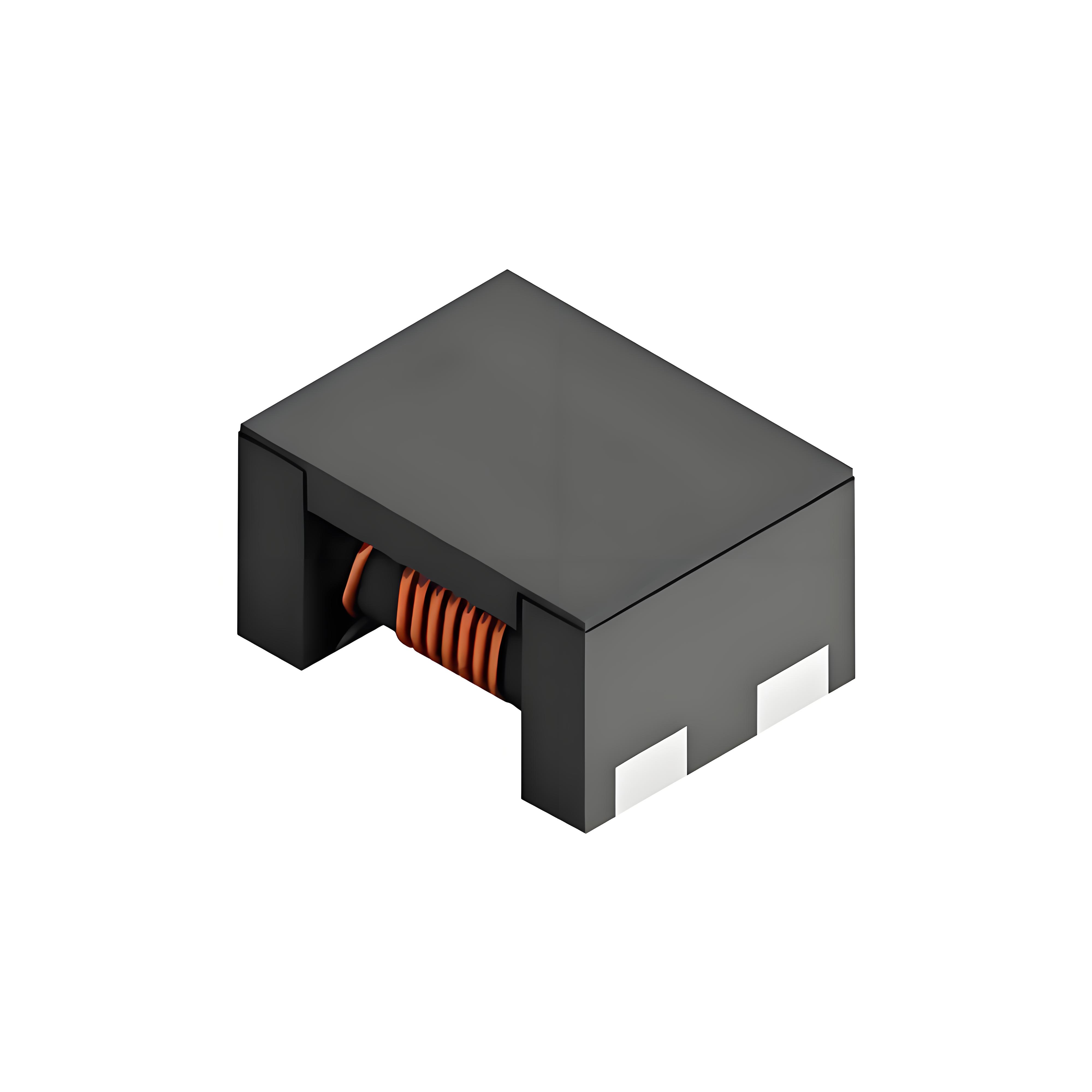
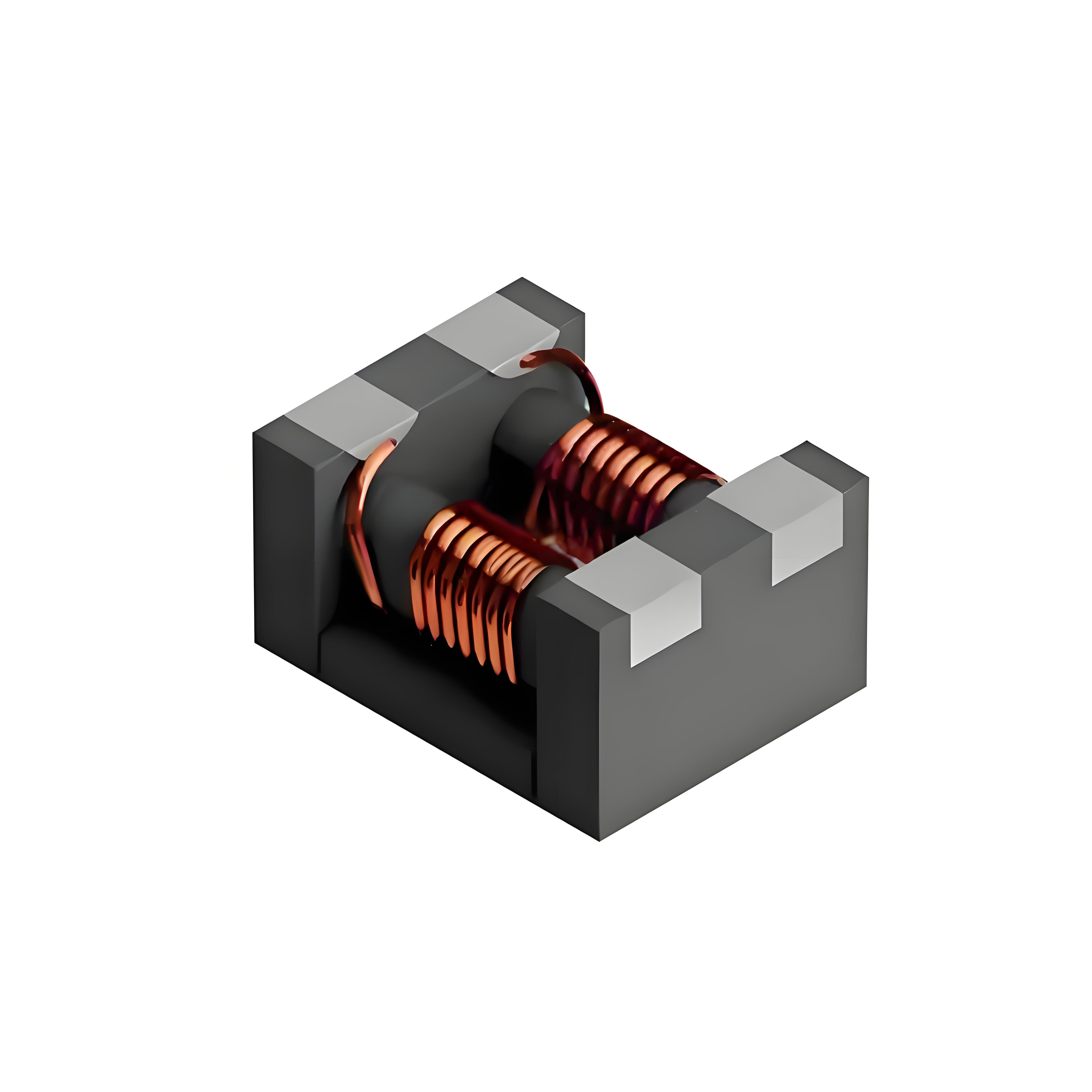
| Wire-wound CM Inductor | Coilcraft 1812CMS-121 | 1 200 | 42 | 35 | 3.2 |
| Wideband CM Choke | TDK ACM45V-102-2PL | 1 000 | 38 | 20 | 4.0 |
3. Bench Problem: 42 dB @ 3.7 GHz on the 28 V Bias Rail
Pre-compliance scan on a 28 V, 3.2 A PA bias line shows a 42 dB peak at 3.7 GHz—8 dB above the 3GPP spurious emission mask. The differential-mode ripple is only 9 mVpp, confirming the noise is purely common mode.

4. Solution: 4-Step Component Selection & Layout
Choose CM choke with ≥ 1 000 Ω @ 3.7 GHz: Coilcraft 1812CMS-121 meets 42 dB attenuation.
Verify current headroom: 3.2 A load vs. 3.2 A rated → 0 % de-rating.
Mount within 5 mm of PA VDD pin to cut stub inductance below 1 nH.
Add copper pour shield (0.3 mm gap) beneath choke to reduce parasitic C < 0.2 pF.
5. Validation Results Table
| Test Condition | Peak @ 3.7 GHz (dBµV) | Margin to 3GPP Limit (dB) | Envelope BW (MHz) | PA Efficiency (%) |
|---|---|---|---|---|
| No suppression | 82 | –8 | 400 | 43.1 |
| Ferrite bead (600 Ω) | 67 | 7 | 360 | 42.9 |
| CM inductor (1 200 Ω) | 40 | 34 | 395 | 43.0 |
6. Quick-Reference Design Tables
6.1 5G Frequency Bands & Recommended CM Chokes
| Band | Center (GHz) | Typical Choke Inductance (µH) | Part Example | Attenuation Target (dB) |
|---|---|---|---|---|
| n78 | 3.5 | 0.12 | Coilcraft 1812CMS-121 | ≥ 42 |
| n79 | 4.7 | 0.10 | TDK ACM45V-102-2PL | ≥ 38 |
| n257 | 28 | 0.05 | Murata DLW21SZ | ≥ 30 |
6.2 Layout Checklist
☐ Place choke within 5 mm of load pin
☐ Keep trace length symmetry < 0.25 mm for balanced suppression
☐ Use via-in-pad to ground shield for parasitic C < 0.2 pF
☐ Verify return path continuity under 10 mil gap
Follow these data-driven steps and the how common mode inductors solve EMI in 5G base stations challenge turns into a predictable 5-minute component swap instead of weeks of trial-and-error.
